Hardware Oriented
Speed Control of Three-Phase Induction Motor Using VFD with Constant V/f Control
Aim
- To understand the principle of Variable Frequency Drive (VFD) operation.
- To study speed control of a three-phase induction motor using V/f control strategy.
- To verify that maintaining a constant V/f ratio ensures constant air-gap flux.
- To analyze performance characteristics such as speed, current, and voltage variation with frequency.
Apparatus & Software
| Sl. No. | Apparatus | Technical Specification | Quantities |
|---|---|---|---|
| 1 | Three-Phase Squirrel Cage Induction Motor | 415 V, 50 Hz, 4-pole (or as per lab nameplate) | 1 |
| 2 | Variable Frequency Drive (VFD) | 3-phase input/output, rated for motor kW rating | 1 |
| 3 | Three-Phase AC Supply | 415 V, 50 Hz | 1 |
| 4 | Voltmeter | AC, appropriate range (0–500 V) | 1 |
| 5 | Ammeter | AC, appropriate range (0–10 A) | 1 |
| 6 | Tachometer / Speed Sensor | Digital, 0–3000 RPM range | 1 |
| 7 | Connecting Leads | As required | As required |
Theory
An induction motor operates on the principle of electromagnetic induction. The three-phase supply applied to the stator windings produces a rotating magnetic field that rotates at synchronous speedsynchronous speedThe speed of the rotating magnetic field in an AC induction machine, determined by supply frequency and number of poles: Ns = 120f / P.. This rotating field induces currents in the short-circuited rotor conductors, which interact with the field to produce torque.
The synchronous speed of an induction motor is given by:
where f is the supply frequency in Hz and P is the number of stator poles. The actual rotor speed N is slightly less than synchronous speed due to slip, which is defined as:
From the synchronous speed equation, it is clear that the motor speed is directly proportional to the supply frequency. A Variable Frequency Drive (VFD) exploits this relationship by converting the fixed-frequency AC mains supply into a variable-frequency, variable-voltage AC output, thereby controlling the motor speed continuously over a wide range without mechanical intervention.
The air-gap flux of an induction motor is proportional to the ratio of the applied voltage to the supply frequency:
To maintain constant air-gap flux — and hence constant torque-producing capability — the V/f ratio must be kept constant as frequency is varied. If this ratio is not maintained, two undesirable conditions arise: a high V/f ratio causes magnetic saturation of the stator core, leading to excessive magnetising current, increased iron losses, and overheating; a low V/f ratio reduces the air-gap flux, which reduces the torque capability of the motor and may cause it to stall under load.
Therefore, constant V/f control ensures uniform torque production and efficient motor operation over a wide speed range. At very low frequencies (below approximately 5–10 Hz), a voltage boost is typically applied to compensate for the stator resistance voltage drop, which becomes significant relative to the applied voltage at low frequencies.
Pre-Lab / Circuit Diagram
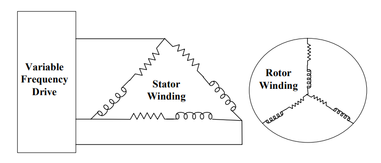
Figure 1: V/f operation of a three-phase induction motor using a Variable Frequency Drive.
Procedure
- Verify all connections between the VFD output terminals and the three-phase induction motor terminals. Ensure phase sequence is correct.
- Ensure proper earthing of the VFD, motor frame, and all metal enclosures. Observe all safety precautions before energizing.
- Configure the VFD in V/f (scalar) control mode using the VFD keypad or parameter menu.
- Set the base frequency to 50 Hz and the corresponding rated voltage (as per motor nameplate) in the VFD parameters.
- Start the VFD at a low frequency (10 Hz). Allow the motor to reach steady state.
- Measure and record the output voltage (V), stator current (A), and motor speed (RPM) using the voltmeter, ammeter, and tachometer respectively.
- Increase the output frequency in steps: 10 Hz → 20 Hz → 30 Hz → 40 Hz → 50 Hz. At each step, allow steady state and record all readings.
- At each frequency step, verify that the output voltage increases proportionally to maintain a constant V/f ratio.
- Calculate the V/f ratio for each observation and the theoretical synchronous speed using Ns = 120f/P.
- Compare the measured motor speed with the calculated synchronous speed and determine the slipslipThe difference between synchronous speed and actual rotor speed, expressed as a fraction of synchronous speed. Slip is zero at no load and increases with load. at each frequency.
- After completing all observations, gradually reduce the frequency back to zero and stop the motor safely.
Simulation / Execution (Not Applicable)
This section is not required for this experiment.
Observations
The following readings were recorded for a 4-pole, 415 V, 50 Hz three-phase squirrel-cagesquirrel-cageA type of induction motor rotor consisting of conducting bars short-circuited by end rings, resembling a squirrel cage. It is robust, low-maintenance, and self-starting. induction motor operated under the constant V/f control strategy. The rated V/f ratio is 415/50 = 8.3 V/Hz. Voltage was scaled proportionally at each frequency step to maintain this ratio.
| S. No. | Frequency (Hz) | Voltage (V) | V/f Ratio (V/Hz) | Theoretical Ns (RPM) | Measured Speed N (RPM) | Current (A) | Slip s |
|---|---|---|---|---|---|---|---|
| 1 | 10 | 83 | 8.3 | 300 | 288 | 3.2 | 0.040 |
| 2 | 20 | 166 | 8.3 | 600 | 582 | 3.4 | 0.030 |
| 3 | 30 | 249 | 8.3 | 900 | 876 | 3.6 | 0.027 |
| 4 | 40 | 332 | 8.3 | 1200 | 1170 | 3.8 | 0.025 |
| 5 | 50 | 415 | 8.3 | 1500 | 1464 | 4.1 | 0.024 |
The measured speed at each frequency is slightly less than the synchronous speed due to slip, which decreases with increasing frequency (and hence increasing speed) as the rotor approaches synchronous speed more closely at higher operating points. The V/f ratio remains constant at 8.3 V/Hz across all steps, confirming the constant flux operation.
Calculations
Theoretical synchronous speed at each frequency for a 4-pole motor (P = 4):
| Frequency (Hz) | Ns = 30f (RPM) |
|---|---|
| 10 | 300 |
| 20 | 600 |
| 30 | 900 |
| 40 | 1200 |
| 50 | 1500 |
V/f ratio verification — the rated V/f ratio at base frequency:
At each step the applied voltage is V = 8.3 × f, confirming constant ratio. For example at 30 Hz: V = 8.3 × 30 = 249 V.
Slip calculation at each operating point:
At 50 Hz: s = (1500 − 1464) / 1500 = 36 / 1500 = 0.024 (2.4%). At 10 Hz: s = (300 − 288) / 300 = 12 / 300 = 0.040 (4.0%). The slip decreases with increasing frequency, reflecting improved rotor efficiency at higher speeds under no-load / light-load conditions.
Results & Analysis
The experiment verifies that the speed of a three-phase induction motor is directly proportional to the supply frequency under constant V/f control.
- The motor speed increased linearly with supply frequency from approximately 288 RPM at 10 Hz to 1464 RPM at 50 Hz, confirming the direct proportionality Ns = 120f/P.
- The V/f ratio was maintained constant at 8.3 V/Hz across all frequency steps (10 Hz to 50 Hz), ensuring constant air-gap flux and stable torque production throughout the speed range.
- The slip decreased from 4.0% at 10 Hz to 2.4% at 50 Hz, indicating that the rotor operated more efficiently (closer to synchronous speed) at higher frequencies under the prevailing light-load conditions.
- The stator current increased slightly from 3.2 A at 10 Hz to 4.1 A at 50 Hz, consistent with the higher power demand at higher speeds and the increased iron losses at higher flux frequencies.
- No abnormal vibration, overheating, or instability was observed during the experiment, confirming that the constant V/f strategy effectively prevents magnetic saturation and flux weakening across the entire tested frequency range.
- The VFD successfully achieved smooth, stepless speed control of the induction motor without requiring any mechanical speed control device, demonstrating the practical advantage of variable frequency drives.
Conclusion
In this experiment, the speed control of a three-phase squirrel-cage induction motor using a Variable Frequency Drive (VFD) with constant V/f control was successfully studied and verified. The motor speed was controlled smoothly over the range of 10 Hz to 50 Hz by varying the VFD output frequency while proportionally scaling the output voltage to maintain a constant V/f ratio of 8.3 V/Hz.
The measured motor speeds at each frequency step closely matched the theoretical synchronous speeds, with small slip values confirming normal induction motor operation. The constant V/f ratio ensured constant air-gap flux at all operating points, preventing magnetic saturation at high voltages and flux weakening at low voltages, thereby maintaining consistent torque capability throughout the speed range. The experiment clearly demonstrates that VFD-based constant V/f speed control is a highly effective, efficient, and flexible method for controlling the speed of three-phase induction motors over a wide range without the mechanical losses associated with traditional speed control methods.
Post-Lab / Viva Voce
- Q: Explain the principle of V/f control and why simply varying the frequency alone (without adjusting voltage) is insufficient for effective speed control of an induction motor.
A: V/f (scalar) control is a method of speed control in which both the output voltage and output frequency of the VFD are varied simultaneously such that their ratio V/f remains constant. The air-gap flux of an induction motor is proportional to V/f (from Faraday's law: the stator back-EMF E ≈ 4.44·f·N·φ, so φ ∝ E/f ≈ V/f for small stator impedance drop). If frequency alone is increased without increasing V, the flux φ decreases proportionally. Reduced flux means the motor cannot produce its rated torque — for the same torque demand, a higher rotor current is needed, causing excessive heating and possibly stalling. Conversely, if frequency is decreased without reducing V, flux increases beyond the rated value, saturating the stator core — this causes a disproportionate increase in magnetising current, large iron losses, overheating, and distorted current waveforms. Constant V/f control avoids both extremes by scaling V linearly with f, maintaining rated flux and hence rated torque capability at all speeds. - Q: Why is constant air-gap flux important in an induction motor, and what are the practical consequences of operating with reduced flux?
A: The air-gap flux is fundamental to torque production in an induction motor. The electromagnetic torque is proportional to the product of the rotor current and the air-gap flux: T ∝ φ·Ir. For a given torque demand, if φ is reduced, the rotor must draw a proportionally higher current to maintain the same torque. This has several practical consequences: (1) Higher rotor copper losses (I²R), causing overheating of the rotor windings and shortening insulation life. (2) Reduced pull-out (maximum) torque — the motor becomes more susceptible to stalling under transient load increases. (3) Poorer power factor, since the reduced flux means less of the stator current contributes to useful torque production and more flows as reactive magnetising current. (4) Instability at low speeds, as the torque margin between the operating point and the pull-out point shrinks. Maintaining constant flux ensures the motor retains its rated torque capability, thermal performance, and stability across the full speed range. - Q: Define slip and explain physically why the slip is higher at low frequencies (low speeds) compared to high frequencies under the constant V/f control strategy, as observed in this experiment.
A: Slip s = (Ns − N)/Ns is the fractional difference between synchronous speed and actual rotor speed. It represents the relative motion between the rotating stator field and the rotor — the rotor always lags slightly behind the stator field, and this lag is what induces rotor currents and produces torque. At low frequencies (low speeds), the stator resistance Rs becomes a significant fraction of the total stator impedance (since the stator reactance Xs = 2πfLs decreases with frequency). The voltage drop across Rs (= Is·Rs) consumes a larger portion of the applied voltage, reducing the voltage actually available to drive the air-gap flux. This effectively reduces the air-gap flux below its ideal value at low frequencies, causing the motor to draw higher rotor currents (and hence higher slip) to produce the required torque. At higher frequencies, Xs dominates Rs, the stator resistance effect becomes negligible, and the motor operates closer to ideal — less slip is needed for the same torque. This is why practical VFDs apply a voltage boost at very low frequencies to compensate for the Rs voltage drop. - Q: What happens if the V/f ratio is set higher than the rated value (over-voltage relative to frequency), and what physical phenomenon limits the maximum V/f ratio that can be applied?
A: If V/f > rated value, the air-gap flux φ exceeds its rated value. The stator core of an induction motor is designed to operate at a specific maximum flux density (typically 1.2–1.7 T for silicon steel laminations). When φ is increased beyond the design value, the core enters magnetic saturation — the B-H curve of the core material becomes highly nonlinear, and a small further increase in flux requires a disproportionately large increase in magnetising current. The practical consequences are: (1) The magnetising current increases sharply (can reach several times the rated value), causing severe overheating of the stator windings. (2) The power factor deteriorates because of the large reactive magnetising current. (3) The distorted non-sinusoidal magnetising current waveform generates harmonic losses and EMI. (4) The core loss (hysteresis and eddy current losses) increases dramatically with both flux density and frequency. The physical limit is the saturation flux density of the core material (typically 1.8–2.0 T for silicon steel), beyond which the permeability collapses and the motor becomes essentially a resistive load rather than an inductive one. - Q: What are the advantages of VFD-based speed control over traditional methods such as rotor resistance control or stator voltage control for three-phase induction motors?
A: VFD-based speed control offers several significant advantages: (1) Efficiency — VFDs control speed by varying frequency, which changes the synchronous speed itself; the motor always operates near synchronous speed (low slip) regardless of the set speed. In contrast, rotor resistance control increases slip (and hence rotor copper losses I²R) to reduce speed — the motor runs inefficiently at low speeds, wasting energy as heat in the external resistors. (2) Speed range — VFDs provide a smooth, continuous speed range from near-zero to above rated speed (field weakening region), whereas rotor resistance control provides only limited, stepped speed reduction. Stator voltage control reduces torque capability severely at reduced voltages. (3) No mechanical wear — VFDs have no mechanical components in the speed control path; rotor resistance controllers require slip rings and carbon brushes (applicable only to wound-rotor motors). (4) Soft starting — VFDs can start the motor at very low frequency and voltage, limiting inrush current to near rated value, whereas direct-on-line starting draws 5–7 times rated current. (5) Regenerative braking — modern VFDs can return kinetic energy to the supply during deceleration. (6) Applicable to squirrel-cage motors — the most rugged, maintenance-free motor type, unlike rotor resistance control which requires wound-rotor motors. - Q: In the constant V/f control experiment, the stator current was observed to increase from 3.2 A at 10 Hz to 4.1 A at 50 Hz. Provide a quantitative explanation for this trend, referencing the motor's equivalent circuit parameters.
A: In the induction motor equivalent circuit, the stator current Is has two main components: the magnetising current Im (which maintains the air-gap flux) and the load current Ir (which produces torque). Under constant V/f control with constant flux, Im remains approximately constant across all frequencies (since φ ∝ V/f = constant, and Im ∝ φ). However, the iron loss component of current (Ic) increases with frequency because core losses Pfe = Physteresis + Peddy ∝ f·B² + f²·B², so both components increase with f. Additionally, at higher frequencies, the stator iron carries higher eddy current losses due to the increased rate of flux change. The stator copper loss I²·Rs also increases with current. In the no-load / light-load conditions of this experiment, the torque component Ir is small and roughly constant (just overcoming friction and windage). Therefore the observed increase from 3.2 A to 4.1 A primarily reflects: (1) the increase in iron loss current Ic with frequency, (2) slightly increased windage and friction losses at higher speeds requiring marginally more torque current, and (3) the increase in stator reactance voltage drop Is·Xs = Is·(2πfLs) with frequency, which slightly shifts the operating point. The 28% current increase from 10 Hz to 50 Hz is consistent with the dominance of frequency-dependent iron loss at light load.
References & Resources (Not Applicable)
This section is not required for this experiment.
Was this experiment helpful?
Your feedback helps us improve
Please Sign In to rate this experiment.