Hardware-Oriented
Pressure Transducer Explorer (Manual Pressure Transducer)
Aim
- To study the operation of a differential amplifier with gain using a pressure transducer.
- To analyze the conversion of pressure transducer output voltage into a standard 4–20 mA current signal for transmission purposes.
- To understand the characteristics and behavior of the pressure transducer with differential amplifier.
- To study pressure control using an On/Off controller.
Apparatus & Software
| Sl. No. | Component | Quantity |
|---|---|---|
| 1 | Scientech 2308 Pressure Transducer Explorer | 1 |
| 2 | Pressure Vessel | 1 |
| 3 | Foot Pump | 1 |
| 4 | Connecting Tube (1.5 meters) | 1 |
| 5 | 2 mm Patch Cords | 5 |
Theory
Pressure and Types of Pressure: Pressure is defined as the force exerted per unit area. In practical systems, pressure is commonly classified as atmospheric, gauge, absolute, and differential pressure. Gauge pressure is measured with respect to atmospheric pressure, while absolute pressure is measured with respect to a perfect vacuum. Differential pressure is the difference between two applied pressures and is widely used in industrial measurements.
Differential Pressure Transducer: A differential pressure transducer measures the difference between two input pressures. It commonly operates on the strain gauge principle. When a pressure difference is applied across a diaphragm, it deforms, causing strain in the attached strain gauges. This results in a change in resistance, which is converted into a small electrical voltage using a Wheatstone bridge circuit. The output voltage is proportional to the applied pressure difference.
Depending on the applied pressures: If P1 = P2, output is zero. If P1 > P2, output is positive. If P2 > P1, output is negative.
Differential Amplifier: The output from the pressure transducer is very small (in millivolts), hence it requires amplification. A differential amplifier amplifies the difference between two input signals while rejecting noise. This makes it suitable for accurate signal processing in industrial environments.
Voltage to Current Conversion (4–20 mA): For long-distance signal transmission, voltage signals are converted into current signals (4–20 mA standard). Current signals are less affected by noise and voltage drops in transmission lines. In this system, 4 mA represents the minimum pressure and 20 mA represents the maximum pressure. The conversion is achieved using a voltage-to-current converter circuit, where output current is proportional to the input voltage.
On/Off Pressure Control: An On/Off controller is a simple control system that maintains pressure within a desired range. It compares the measured pressure with a reference value. If pressure is below the set point, the controller turns ON the system. If pressure exceeds the set point, the controller turns OFF the system. This type of control is widely used due to its simplicity, though it may cause small oscillations around the set point.
Pre-Lab / Circuit Diagram
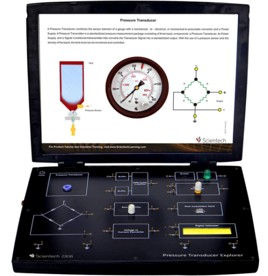
Figure 1: Pressure Transducer Experimental Kit Setup (Scientech 2308).
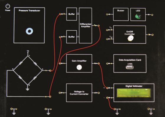
Figure 2: Circuit Diagram for Differential Amplifier with Pressure Transducer.
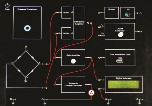
Figure 3: Circuit Diagram for Voltage to Current Conversion (4–20 mA).
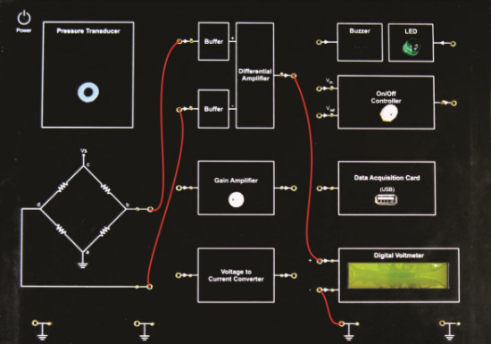
Figure 4: Circuit Diagram for Pressure Measurement using Differential Transducer.
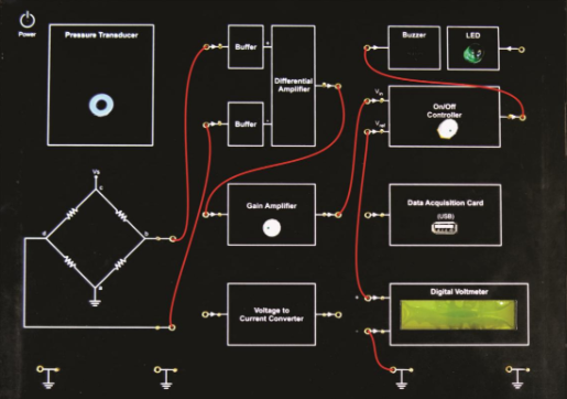
Figure 5: Circuit Diagram for On/Off Pressure Control System.
Procedure
- Fill the pressure vessel up to a safe limit (maximum 60 psi) using the foot pump. Ensure the outlet valve is initially closed.
- Connect the pressure vessel outlet to one inlet (P1 or P2) of the pressure transducer using the connecting tube. Keep the other inlet open to atmospheric pressure.
- Switch ON the Scientech 2308 Pressure Transducer Explorer and make connections as per the required circuit diagram.
- Differential Amplifier with Gain: Open the valve slowly to apply pressure to the transducer. Observe the amplified output voltage on the DVM. Record readings for different pressure values.
- Voltage to Current Conversion (4–20 mA): Connect the voltage-to-current converter circuit. Vary the pressure gradually. Observe and record the corresponding output current.
- Differential Pressure Measurement: Measure the direct output voltage from the transducer without amplification. Note the variation of output with applied pressure.
- On/Off Pressure Control: Set the reference voltage using the potentiometer. Increase pressure slowly and observe the switching action. Note the condition when the controller turns ON/OFF (LED/Buzzer indication).
- Record all observations and plot the required graphs.
- After completion, release the pressure slowly, switch OFF the setup, and disconnect all connections.
Simulation / Execution (Not Applicable)
This section is not required for this experiment.
Observations
Table 1: Differential Amplifier with Gain — Pressure vs Differential Output Voltage with Gain
| Pressure (psi) | Differential Output with Gain (V) |
|---|---|
| 60 | 2.50 |
| 55 | 2.32 |
| 50 | 1.97 |
| 45 | 1.75 |
| 40 | 1.44 |
| 30 | 0.90 |
| 25 | 0.68 |
| 20 | 0.42 |
| 15 | 0.14 |
| 10 | -0.12 |
| 5 | -0.35 |
| 0 | -0.80 |
Table 2: Voltage to Current Conversion — Pressure vs Current Output
| Pressure (psi) | Current Output (mA) |
|---|---|
| 55 | 13.25 |
| 50 | 12.00 |
| 45 | 10.70 |
| 40 | 9.80 |
| 30 | 8.50 |
| 35 | 7.20 |
| 20 | 6.09 |
| 15 | 4.85 |
| 10 | 3.90 |
| 5 | 2.75 |
| 0 | 0.70 |
Table 3: Differential Output using Pressure Transducer — Pressure vs Differential Output Voltage (without gain)
| Pressure (psi) | Differential Output (V) |
|---|---|
| 55 | 1.08 |
| 50 | 0.92 |
| 45 | 0.78 |
| 40 | 0.67 |
| 30 | 0.50 |
| 25 | 0.36 |
| 20 | 0.22 |
| 15 | -0.06 |
| 10 | -0.08 |
| 5 | -0.22 |
| 0 | -0.42 |
Table 4: On/Off Pressure Control using Comparator — Set Voltage vs Switching Pressure
| Set Voltage (V) | Pressure (psi) |
|---|---|
| 1.70 | 42.5 |
| 1.83 | 46.0 |
| 1.94 | 48.0 |
| 2.12 | 51.0 |
| 2.31 | 53.0 |
Calculations
The amplifier gain can be estimated from the differential output readings. For the Differential Amplifier with Gain, the sensitivity (slope) is computed from the linear region of Table 1:
For the Voltage-to-Current conversion, the relationship between pressure and output current is approximately linear. The slope from Table 2 (using endpoints 0 psi → 0.70 mA and 55 psi → 13.25 mA):
For the On/Off controller, the relationship between set voltage and switching pressure is approximately linear (from Table 4, using endpoints):
This confirms that a higher set voltage corresponds to a higher switching pressure threshold, validating the comparator-based On/Off control operation.
Results & Analysis
- The differential output voltage of the pressure transducer varied proportionally with the applied pressure difference, confirming the linear characteristics of the Wheatstone bridge-based strain gauge transducer.
- When amplified using the differential amplifier with gain, the output signal showed improved magnitude and better sensitivity (approx. 0.055 V/psi), making it suitable for further signal processing.
- The voltage-to-current conversion successfully produced an output current proportional to the applied pressure. Although the observed current range (0.70–13.25 mA) did not fully span the ideal 4–20 mA standard, the linear trend was clearly demonstrated.
- In the On/Off pressure control experiment, the comparator switched the controller at specific pressure levels corresponding to the set reference voltage, confirming proper functioning of the control system.
- Minor non-linearities in the differential output (Table 3, readings at 10–15 psi) may be attributed to hysteresis in the diaphragm or contact resistance variation in the Wheatstone bridge at low pressures.
- The consistent linear response across all sub-experiments validates the suitability of the Scientech 2308 system for teaching pressure transducer characteristics.
Conclusion
The characteristics of the pressure transducer along with signal conditioning circuits were successfully studied and analyzed. It was observed that the differential output voltage of the pressure transducer varied proportionally with the applied pressure difference. When amplified using a differential amplifier, the output signal showed improved magnitude and better sensitivity, making it suitable for further processing. The voltage-to-current conversion was also studied, where the transducer output was converted into a standard 4–20 mA signal. It was observed that the output current increased with pressure, demonstrating reliable transmission characteristics suitable for industrial applications over long distances. In the On/Off controlon/off controlA rudimentary feedback control mechanism that switches the output completely ON or completely OFF depending on whether the process variable is below or above a setpoint, often causing oscillations (chattering). experiment, the system successfully responded to the set reference voltage, and the controller switched ON and OFF at specific pressure levels, indicating proper functioning of the comparator-based control system. Overall, the experiment verified the effective measurement, amplification, transmission, and control of pressure using a pressure transducer system.
Post-Lab / Viva Voce
- Q: What is the working principle of a differential pressure transducer?
A: It operates on the strain gauge principle. A pressure difference applied across a diaphragm causes it to deform, straining the attached strain gauges and changing their resistance. This resistance change is converted into a small voltage by a Wheatstone bridge circuit, with the output voltage proportional to the pressure difference. - Q: Why does the differential output go negative at low pressures (e.g., 0–10 psi)?
A: At zero applied gauge pressure, the reference side of the differential transducer is at atmospheric pressure. Any offset in the bridge or small residual stress in the diaphragm produces a negative output at the reference state. This is a zero offset that can be nulled through calibration. - Q: Why is a differential amplifier used instead of a simple amplifier?
A: A differential amplifier amplifies only the difference between its two inputs while rejecting common-mode noise (e.g., electromagnetic interference, power supply fluctuations). This is essential for accurate amplification of the small millivolt-level transducer output in industrial environments. - Q: Why is the 4–20 mA signal preferred over a voltage signal for long-distance transmission?
A: Current signals are immune to resistive voltage drops in long cable runs, unlike voltage signals which attenuate with cable resistance. The 4 mA live-zero also allows fault detection: a 0 mA reading indicates a broken wire rather than a zero-pressure condition. - Q: What is the significance of the 4 mA live-zero in the 4–20 mA standard?
A: The 4 mA minimum (live-zero) distinguishes a valid zero-measurement signal from a fault condition such as a broken wire or loss of power (which would give 0 mA). This enables fault detection without additional diagnostics. - Q: What is an On/Off controller and what are its limitations?
A: An On/Off (bang-bang) controller switches the output fully ON or fully OFF based on whether the measured variable is below or above the set point. Its main limitation is that it causes continuous oscillation (hunting) around the set point rather than settling to a stable value, which may be unacceptable in precision applications. - Q: How does the Wheatstone bridge convert strain into a voltage?
A: The bridge consists of four resistors, with strain gauges forming one or more arms. When pressure deforms the diaphragm, the gauge resistance changes, unbalancing the bridge and producing an output voltage proportional to the resistance change, and hence to the applied pressure. - Q: What are the types of pressure and how do they differ?
A: Gauge pressure is measured relative to atmospheric pressure; absolute pressure is measured relative to a perfect vacuum; differential pressure is the difference between two process pressures. Gauge pressure = Absolute pressure − Atmospheric pressure. - Q: Why does the output current in Table 2 not reach exactly 4 mA and 20 mA?
A: The 4–20 mA range requires precise calibration of the voltage-to-current converter (zero and span adjustments). Without careful trimming of the offset and gain potentiometers, the output spans a slightly different range, as seen in the experimental results (0.70–13.25 mA). - Q: What precautions must be taken during this experiment?
A: The pressure vessel must not be filled beyond the rated maximum (60 psi). The outlet valve should be opened slowly and gradually. Connections must be checked before switching ON power. After the experiment, pressure must be released slowly to avoid sudden stress on the transducer diaphragm.
References & Resources (Not Applicable)
This section is not required for this experiment.
Was this experiment helpful?
Your feedback helps us improve
Please Sign In to rate this experiment.