Hardware-Oriented
Study of Flow Rate with Magnetic Flow Meter
Aim
To study and understand the measurement of flow rate using a magnetic flow meter.
Apparatus & Software
| Sl. No. | Component | Quantity |
|---|---|---|
| 1 | Scientech 3008 Magnetic Flow Meter | 1 |
| 2 | Patch Cords | As required |
Theory
Flow measurement is an important aspect of industrial processes. Flow meters are broadly classified into two types: direct and indirect measurement.
Direct flow measurement (positive displacement) traps and measures fixed volumes of fluid and counts the number of fill-and-discharge cycles. It offers high accuracy and is used for low flow rate applications. Examples include piston, rotary vane, and oval gear flow meters.
Indirect flow measurement determines flow rate by measuring fluid velocity or energy changes. The volumetric flow rate is given by:
where Q is the volumetric flow rate, A is the pipe cross-sectional area, V is the fluid velocity, and k is a scaling factor. Indirect devices include differential pressure meters, turbine meters, vortex meters, ultrasonic meters, and magnetic flow meters.
The nature of fluid flow is characterized by the Reynolds number (Re = ρVD/μ): laminar flow occurs at Re < 2000 (smooth, orderly), turbulent flow at Re > 5000 (chaotic), and transitional flow in between. Viscosity, which varies with temperature, significantly affects flow behavior and measurement accuracy.
A magnetic flow meter (magmeter) is an indirect flow measuring device for conductive fluids. It consists of an inline sensor and a transmitter. It operates on Faraday's law of electromagnetic induction: when a conductive fluid flows through a magnetic field applied perpendicular to the flow, an EMF is induced proportional to the fluid velocity:
where E is the induced voltage (V), B is the magnetic field strength (T), D is the pipe diameter (m), V is the fluid velocity (m/s), and k is a constant. The induced voltage is sensed by electrodes mounted on the pipe wall and processed by the transmitter to output a 4–20 mA signal proportional to the flow rate.
Pre-Lab / Circuit Diagram
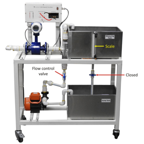
Figure 1: Scientech 3008 Magnetic Flow Meter experimental kit setup.
Procedure
- Ensure that the drain valve of the measuring tank is properly closed before starting the experiment.
- Check that the sump tank contains sufficient water to avoid dry running of the pump.
- Switch ON the power supply and start the pump from the control panel.
- Adjust the flow rate by rotating the flow control valve to a desired position.
- Simultaneously start the timer when the pump is switched ON.
- After the fixed time interval (30 s or 60 s), switch OFF the pump and timer together.
- Record the flow rate (LPH) and output current (mA) displayed on the magnetic flow meter transmitter.
- Measure the water level collected in the measuring tank using the calibrated scale and calculate the actual volume collected (L × W × H / 1000).
- Calculate the volume predicted by the flow meter (Flow Rate × Time / 3600) and compare with the actual volume.
- Open the drain valve to release the collected water and reset the setup.
- Repeat the procedure for different flow control valve settings and time intervals, recording all observations in the table.
Simulation / Execution (Not Applicable)
This section is not required for this experiment.
Observations
Readings were taken for 10 different flow conditions by varying the flow control valve position and measurement time. The measuring tank dimensions are 50 cm (L) × 35 cm (W). The actual volume is calculated from the measured water level; the calculated volume is derived from the magmeter flow rate reading.
| S. No. | Time (s) | Flow Rate (LPH) | Current (mA) | Level (cm) | Actual Vol (L) | Calc Vol (L) |
|---|---|---|---|---|---|---|
| 1 | 30 | 1042 | 17.9 | 5.0 | 8.75 | 8.68 |
| 2 | 30 | 1007 | 17.4 | 4.8 | 8.40 | 8.39 |
| 3 | 30 | 596 | 11.9 | 2.9 | 5.05 | 4.97 |
| 4 | 60 | 498 | 12.8 | 4.8 | 8.40 | 8.30 |
| 5 | 60 | 602 | 12.0 | 5.8 | 10.15 | 10.03 |
| 6 | 30 | 1002 | 17.4 | 4.8 | 8.40 | 8.35 |
| 7 | 30 | 1024 | 17.6 | 4.9 | 8.58 | 8.53 |
| 8 | 30 | 936 | 16.5 | 4.5 | 7.88 | 7.80 |
| 9 | 60 | 720 | 13.5 | 6.9 | 12.10 | 12.00 |
| 10 | 30 | 850 | 15.8 | 4.1 | 7.18 | 7.08 |
Calculations
For each reading, two volumes are computed and compared. The measuring tank cross-section is 50 cm × 35 cm = 1750 cm².
General formulas:
Reading 1 (t = 30 s, Q = 1042 LPH, H = 5.0 cm):
Reading 2 (t = 30 s, Q = 1007 LPH, H = 4.8 cm):
The percentage error between calculated and actual volume for Reading 1:
Similarly, all readings show percentage errors below 1.5%, confirming the high accuracy of the magnetic flow meter across the tested flow range (498–1042 LPH).
Results & Analysis
- The output current of the magnetic flow meter increased directly with the flow rate, ranging from approximately 11.9 mA at 596 LPH to 17.9 mA at 1042 LPH, consistent with the 4–20 mA current loop output convention.
- The calculated volumes (from flow rate × time) agreed closely with the actual volumes (from tank level measurement) across all 10 readings, with maximum discrepancies under 1.5%, confirming the accuracy and reliability of the magnetic flow meter.
- The experiment validated Faraday's law of electromagnetic induction as the working principle: the induced voltage and hence the output current increased proportionally with increasing fluid velocity and flow rate.
- Readings 4 and 5 (60 s duration) produced larger collected volumes than 30 s readings, as expected, demonstrating the time-proportional nature of volumetric flow measurement.
- Minor discrepancies between actual and calculated volumes arise from water level reading parallax error, residual pipe draining after pump shutdown, and slight valve position instability during measurement.
Conclusion
The experiment on flow rate measurement using a magnetic flow meter was carried out successfully. It was observed that the output current increased with an increase in flow rate, confirming the direct relationship between flow and the induced signal based on Faraday's law of electromagnetic induction. The readings obtained from the flow meter showed consistent behavior across different flow conditions. The calculated flow values using the flow rate and time were found to be in close agreement with the actual volumes measured from the tank level, with minor deviations due to experimental and observational errors. Overall, the magnetic flow meter demonstrated reliable and accurate performance for measuring the flow of conductive fluids, validating its suitability for industrial flow measurement applications.
Post-Lab / Viva Voce
- Q: What is the working principle of a magnetic flow meter?
A: It uses Faraday's law: a conductive fluid flowing through a magnetic field generates an induced EMF (E = k·B·D·V) proportional to the fluid velocity, which is measured by electrodes. - Q: Why can a magnetic flow meter only measure conductive fluids?
A: The working principle requires the fluid to act as a moving conductor to generate an EMF; non-conductive fluids (e.g., hydrocarbons, oil) do not carry ions and produce no measurable induced voltage. - Q: What is the minimum conductivity required for a fluid to be measurable by a magmeter?
A: Typically around 5 µS/cm; most aqueous solutions including water, acids, and slurries meet this requirement. - Q: Why does the magmeter output a 4–20 mA signal rather than a 0–20 mA signal?
A: The 4 mA live-zero allows distinction between a zero flow reading (4 mA) and a broken wire or power failure (0 mA), enabling fault detection. - Q: What are the advantages of a magnetic flow meter over a differential pressure flow meter?
A: Magmeters have no moving parts, no pressure drop, are unaffected by viscosity, density, or flow profile, and can handle slurries and corrosive fluids. - Q: What is the Reynolds number and how does flow type affect magmeter accuracy?
A: Re = ρVD/μ; magmeters are accurate for both laminar and turbulent flows above Re ≈ 5000, but require a fully developed flow profile — typically 5D upstream and 2D downstream straight pipe lengths. - Q: Why is the measuring tank closed and the timer started simultaneously with the pump?
A: To ensure that the collected volume corresponds exactly to the timed flow period — any time offset between starting the pump and the timer introduces a systematic volume error. - Q: What causes the small difference between the calculated volume (from magmeter) and the actual volume (from tank level) observed in the results?
A: Sources include parallax error in reading the tank scale, residual water draining from the pipe after the pump stops, and minor valve position drift during measurement. - Q: Can a magmeter measure bidirectional flow? How?
A: Yes — the polarity of the induced EMF reverses when flow direction reverses, and the transmitter detects the sign of the electrode voltage to indicate both magnitude and direction of flow. - Q: What is the difference between laminar and turbulent flow, and why does viscosity affect this?
A: In laminar flow (Re < 2000) fluid moves in parallel layers; in turbulent flow (Re > 5000) it is chaotic. Higher viscosity increases resistance to relative motion between layers, promoting laminar flow at lower velocities.
References & Resources (Not Applicable)
This section is not required for this experiment.
Was this experiment helpful?
Your feedback helps us improve
Please Sign In to rate this experiment.